Toolpack:Create OC3 STM1 Configuration A
(→Applies to version(s): v2.9.) |
|||
| (5 intermediate revisions by one user not shown) | |||
| Line 1: | Line 1: | ||
| − | |||
{{DISPLAYTITLE:Create an OC3/STM1 Configuration}} | {{DISPLAYTITLE:Create an OC3/STM1 Configuration}} | ||
| + | {| class="wikitable" | ||
| + | |- | ||
| + | |rowspan="2"|This article applies to: | ||
| + | |'''Product''' | ||
| + | |'''Version''' | ||
| + | |- | ||
| + | |Tmedia | ||
| + | |2.9, 2.10, 3.0, 3.2 | ||
| + | |} | ||
| + | |||
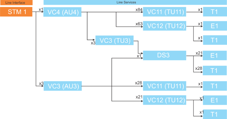
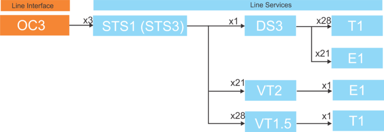
| + | The STM1 and OC3 line interfaces can be configured to suit many needs, as shown in the STM1 and OC3 Configuration overview images. Each configuration begins with the creation of a line interface, which is followed by a parent line service. In turn, the parent line service is followed by one or more child line services. Each line service is assigned its payload type and this defines the capacity of the line service. | ||
| − | |||
'''STM1 Configuration Overview''' | '''STM1 Configuration Overview''' | ||
Latest revision as of 15:24, 24 November 2020
| This article applies to: | Product | Version |
| Tmedia | 2.9, 2.10, 3.0, 3.2 |
The STM1 and OC3 line interfaces can be configured to suit many needs, as shown in the STM1 and OC3 Configuration overview images. Each configuration begins with the creation of a line interface, which is followed by a parent line service. In turn, the parent line service is followed by one or more child line services. Each line service is assigned its payload type and this defines the capacity of the line service.
STM1 Configuration Overview
Multiple configuration paths are possible. An STM1 line interface begins with a VC4 line service. This line service could either have a VC3, VC11, or VC12 line service. For example, you could 1) configure one STM1 line interface with an AU4 payload, followed by 2) one VC4 line service with a TU12 payload, followed by 3) 63 VC12 line servcies with E1 payloads per VC4, followed by 4) one E1 line service for each VC12.
OC3 Configuration Overview
Configuration Example 1: STM1->1x VC4->63x VC12->1x E1
- In this configuration, create one STM1 line interface. Then create one VC4 line service for the STM1 line interface. To the VC4 line service create up to 63 VC12 line services. Finally, to each VC12 line service assign one E1 line service.
| (Step 1) Create an STM1 Line Interface |
(Step 2) Create a VC4 Line Service |
(Step 3) Create VC12 Line Services |
(Step 4) Create an E1 Line Service |
|---|---|---|---|
|
|
|
|
Configuration Example 2: STM1->3x VC3->21x VC12->1x E1
- In this configuration, create one STM1 line interface. Then create three VC3 line services for the STM1 line interface. For each VC3 line service create up to 21 VC12 line services. Finally, to each VC12 line service assign one E1 line service.
| (Step 1) Create an STM1 Line Interface |
(Step 2) Create a VC3 Line Service |
(Step 3) Create VC12 Line Services |
(Step 4) Create an E1 Line Service |
|---|---|---|---|
|
|
|
|
Configuration Example 3: OC3->3x STS3->28x VT1.5->1x T1
In this configuration, create one OC3 line interface. Then create up to three STS1 line services for the OC3 line interface. To each STS1 line service create up to 28 VT1.5 line services. Finally, to each VC12 line service assign one T1 line service.
| (Step 1) Create an OC3 Line Interface |
(Step 2) Create STS1 Line Services |
(Step 3) Create VT1.5 Line Services |
(Step 4) Create an E1 Line Service |
|---|---|---|---|
|
|
|
|


