FreeSBC:SIP Trunking:Example A
(→SBC Use Cases) |
|||
| (4 intermediate revisions by 2 users not shown) | |||
| Line 1: | Line 1: | ||
=== '''''Applies to version: v3.0''''' === | === '''''Applies to version: v3.0''''' === | ||
| − | {{DISPLAYTITLE: | + | {{DISPLAYTITLE:ProSBC:SIP Trunking:Example}} |
=Introduction= | =Introduction= | ||
| − | The SIP Trunking Example Configuration | + | The SIP Trunking Example Configuration provides you with a step by step SIP trunking Configuration of [[ProSBC|ProSbc]] systems, using the Web Portal configuration tool. Complete general installation configuration steps, before you begin configuring your specific scenario. |
=SIP Trunking Example= | =SIP Trunking Example= | ||
| Line 10: | Line 10: | ||
==Prerequisites== | ==Prerequisites== | ||
| − | [[ | + | [[ProSBC|ProSBC]] devices must be installed as described in their respective [[Product_Installation_SBC|installation guides]]. |
=IP Network Configuration= | =IP Network Configuration= | ||
| Line 44: | Line 44: | ||
*Enter a name for the VLAN | *Enter a name for the VLAN | ||
*If the port is to be used untagged, make sure '''Untagged''' is checked. | *If the port is to be used untagged, make sure '''Untagged''' is checked. | ||
| − | *If the port is to be used with | + | *If the port is to be used with an 802.1Q tag, uncheck '''Untagged''' and enter a VLAN ID. |
*Click '''Create''' | *Click '''Create''' | ||
| Line 83: | Line 83: | ||
*Enter a name for the VLAN | *Enter a name for the VLAN | ||
*If the port is to be used untagged, make sure '''Untagged''' is checked. | *If the port is to be used untagged, make sure '''Untagged''' is checked. | ||
| − | *If the port is to be used with | + | *If the port is to be used with an 802.1Q tag, uncheck '''Untagged''' and enter a VLAN ID. |
*Click '''Create''' | *Click '''Create''' | ||
| Line 110: | Line 110: | ||
*Select 1 or more services to use for the IP interface (RTP and SIP). | *Select 1 or more services to use for the IP interface (RTP and SIP). | ||
*Select the '''Host VLAN''' from which IP packets will exit. | *Select the '''Host VLAN''' from which IP packets will exit. | ||
| − | *Indicate whether or not to use DHCP to automatically get an IP address for this port. (selecting this option removes the need to enter | + | *Indicate whether or not to use DHCP to automatically get an IP address for this port. (selecting this option removes the need to enter an IP address, Netmask, and Gateway) |
*Enter an '''IP address''' | *Enter an '''IP address''' | ||
*Enter a '''Netmask''' | *Enter a '''Netmask''' | ||
| Line 136: | Line 136: | ||
*Select 1 or more services to use for the IP interface (RTP and SIP). | *Select 1 or more services to use for the IP interface (RTP and SIP). | ||
*Select the '''Host VLAN''' from which IP packets will exit. | *Select the '''Host VLAN''' from which IP packets will exit. | ||
| − | *Indicate whether or not to use DHCP to automatically get an IP address for this port. (selecting this option removes the need to enter | + | *Indicate whether or not to use DHCP to automatically get an IP address for this port. (selecting this option removes the need to enter an IP address, Netmask, and Gateway) |
*Enter an '''IP address''' | *Enter an '''IP address''' | ||
*Enter a '''Netmask''' | *Enter a '''Netmask''' | ||
| Line 217: | Line 217: | ||
=SIP NAP= | =SIP NAP= | ||
| − | A Network Access Point or NAP represents the entry point to another network or destination peer (e.g. SIP proxy,SIP trunk, etc) | + | A Network Access Point or NAP represents the entry point to another network or destination peer (e.g. SIP proxy, SIP trunk, etc) |
==SIP NAP Configuration for Wide Area Network== | ==SIP NAP Configuration for Wide Area Network== | ||
| Line 331: | Line 331: | ||
==Access Control List== | ==Access Control List== | ||
| − | + | ProSBC will automatically create Access Control List for each NAP you created. | |
[[Image:SIP_Access_Control_List_1.png]] | [[Image:SIP_Access_Control_List_1.png]] | ||
| − | If you double click one of the created ACL, you will see | + | If you double click one of the created ACL, you will see ProSBC only accept the calls if the source IP matches. In this sample; the calls from 192.168.1.10 will be accepted only. |
| Line 369: | Line 369: | ||
| − | 4- Verify that the '''"Route was successfully created"''' message appears | + | 4- Verify that the '''" Route was successfully created"''' message appears and that the new route is listed in the Routeset list |
[[Image:Route_Trunk_to_Server_1.png]] | [[Image:Route_Trunk_to_Server_1.png]] | ||
| Line 395: | Line 395: | ||
| − | 4- Verify that the '''"Route was successfully created"''' message appears | + | 4- Verify that the '''" Route was successfully created"''' message appears and that the new route is listed in the Route set list |
[[Image:Route_Server_to_Trunk_1.png]] | [[Image:Route_Server_to_Trunk_1.png]] | ||
| − | == | + | =Activating the Configuration= |
| − | + | ||
| − | ==SBC Turorial Guide V3.0 | + | Changes made to the configuration of the ProSBC units are stored in the OAM&P Configuration and Logging database. In order for changes to be used by the system, they must first be activated. This is done at the system level and accessed from the Navigation panel. |
| + | |||
| + | Check the following link for activating the configuration; | ||
| + | |||
| + | [[Toolpack:Activating_the_Configuration_D]] | ||
| + | |||
| + | =SBC Use Cases= | ||
| + | [[Toolpack:Tsbc Use Cases A|SBC Use Cases]] | ||
| + | |||
| + | =SBC Turorial Guide V3.0= | ||
[[Tmedia Tsig Tdev Tutorial Guide v3.0|Version 3.0]] | [[Tmedia Tsig Tdev Tutorial Guide v3.0|Version 3.0]] | ||
[[Category:Revise on Major]] | [[Category:Revise on Major]] | ||
Latest revision as of 07:25, 22 January 2021
Contents |
Applies to version: v3.0
Introduction
The SIP Trunking Example Configuration provides you with a step by step SIP trunking Configuration of ProSbc systems, using the Web Portal configuration tool. Complete general installation configuration steps, before you begin configuring your specific scenario.
SIP Trunking Example
Prerequisites
ProSBC devices must be installed as described in their respective installation guides.
IP Network Configuration
Virtual Port Configuration for Wide Area Network
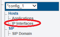
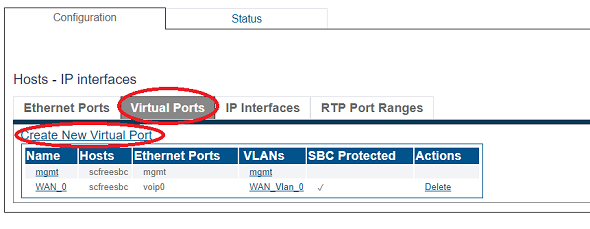
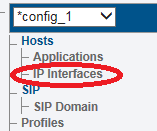
1. Select IP Interfaces from the navigation panel
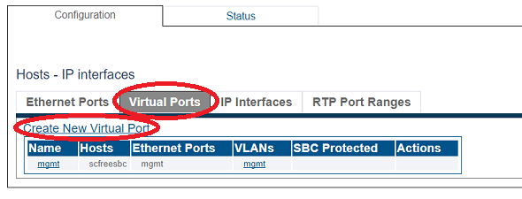
2. Click the Virtual Ports tab.
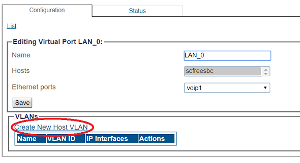
- Click Create New Virtual Port
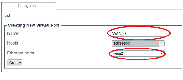
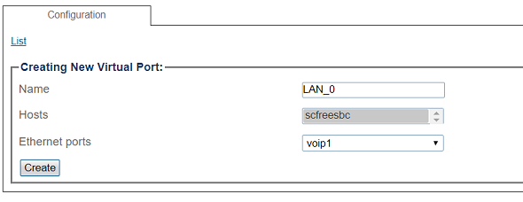
3. Configure the virtual port.
- Enter a name for the virtual port
- Select the host(s) to which the virtual port is assigned
- Select a physical port to which the virtual port is assigned
- Click Create
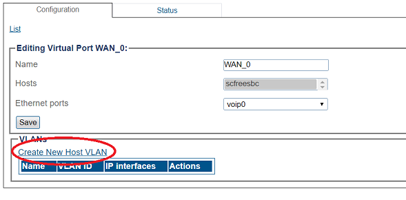
4. Create a VLAN that uses this virtual port
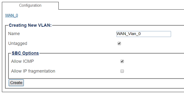
- Click Create new Host VLAN
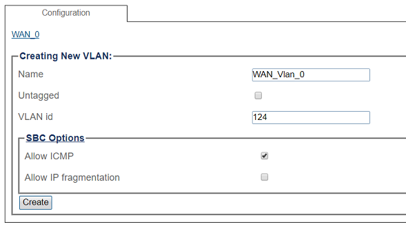
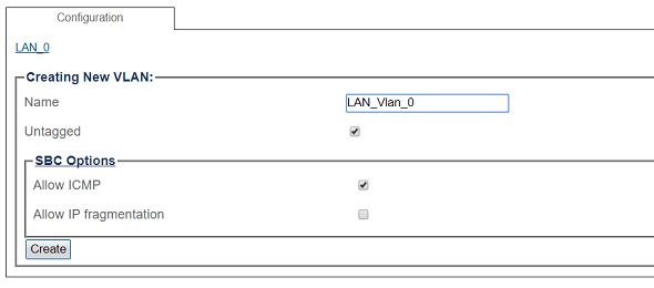
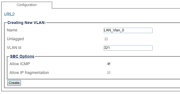
5. Configure the new VLAN
- Enter a name for the VLAN
- If the port is to be used untagged, make sure Untagged is checked.
- If the port is to be used with an 802.1Q tag, uncheck Untagged and enter a VLAN ID.
- Click Create
OR
Virtual Port Configuration for Local Area Network
1. Select IP Interfaces from the navigation panel
2. 2. Click the Virtual Ports tab.
- Click Create New Virtual Port
3. Configure the virtual port.
- Enter a name for the virtual port
- Select the host(s) to which the virtual port is assigned
- Select a physical port to which the virtual port is assigned
- Click Create
4. Create a VLAN that uses this virtual port
- Click Create new Host VLAN
5. Configure the new VLAN
- Enter a name for the VLAN
- If the port is to be used untagged, make sure Untagged is checked.
- If the port is to be used with an 802.1Q tag, uncheck Untagged and enter a VLAN ID.
- Click Create
OR
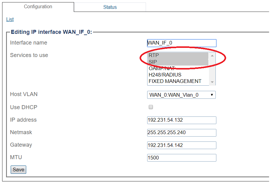
Configuring IP Interface for Wide Area Network
1. Select IP Interfaces from the navigation panel:
2. Click the IP Interfaces tab.
- Click Create New IP Interface
3. Configure the IP interface:
- Enter a name for the interface
- Select 1 or more services to use for the IP interface (RTP and SIP).
- Select the Host VLAN from which IP packets will exit.
- Indicate whether or not to use DHCP to automatically get an IP address for this port. (selecting this option removes the need to enter an IP address, Netmask, and Gateway)
- Enter an IP address
- Enter a Netmask
- Enter a gateway address
- Click Save
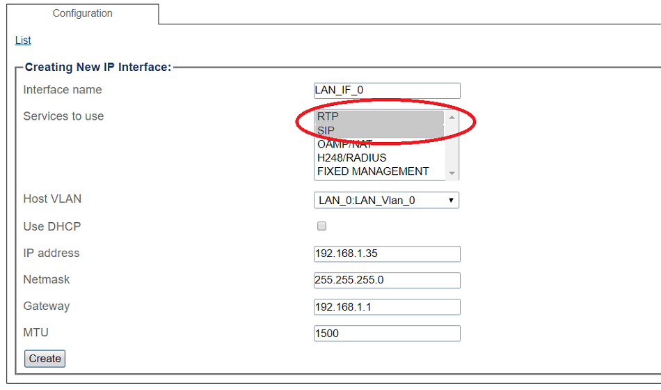
Configuring IP Interface for Local Area Network
1. Select IP Interfaces from the navigation panel:
2. Click the IP Interfaces tab.
- Click Create New IP Interface
3. Configure the IP interface:
- Enter a name for the interface
- Select 1 or more services to use for the IP interface (RTP and SIP).
- Select the Host VLAN from which IP packets will exit.
- Indicate whether or not to use DHCP to automatically get an IP address for this port. (selecting this option removes the need to enter an IP address, Netmask, and Gateway)
- Enter an IP address
- Enter a Netmask
- Enter a gateway address
- Click Save
SIP Stack Configuration
You must configure SIP signaling for your system. The first step in doing so is to create a SIP stack:
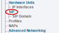
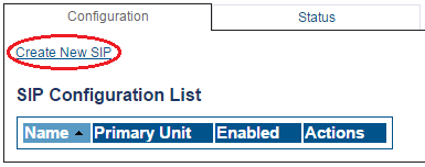
1- Click SIP in the navigation panel
2- Click Create New Sip
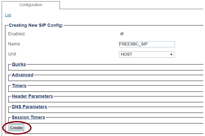
3- Create the new SIP stack:
- Verify that the box labeled Enabled is checked
- Enter a name for the stack
- Click Create
SIP Transport Server Configuration for Wide Area Network
1- Click SIP in the navigation panel
2- Select a SIP stack for which you wish to create a transport server
3- Click Create New Transport Server
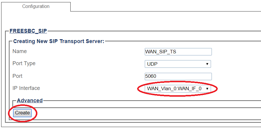
4- Create the new SIP transport server:
- Enter a name for the server
- Select an appropriate port type
- Select an appropriate host IP interface
- Click Create
SIP Transport Server Configuration for Local Area Network
1- Click SIP in the navigation panel
2- Select a SIP stack for which you wish to create a transport server
3- Click Create New Transport Server
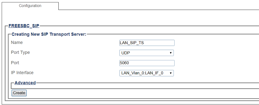
4- Create the new SIP transport server:
- Enter a name for the server
- Select an appropriate port type
- Select an appropriate host IP interface
- Click Create
SIP NAP
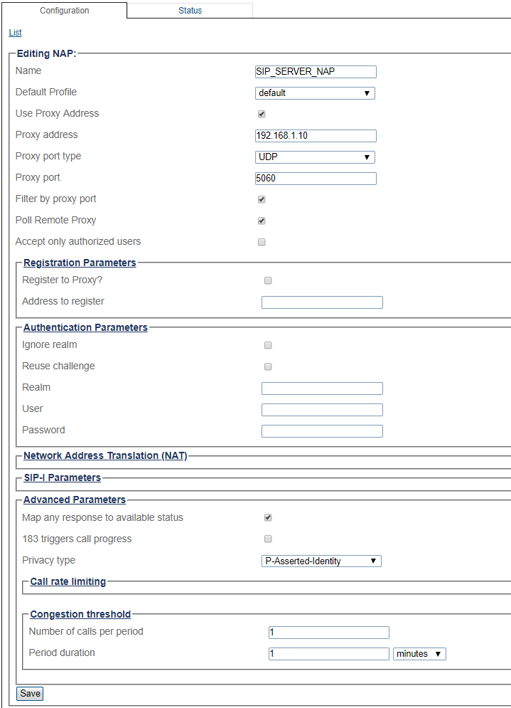
A Network Access Point or NAP represents the entry point to another network or destination peer (e.g. SIP proxy, SIP trunk, etc)
SIP NAP Configuration for Wide Area Network
To create a new NAP:
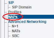
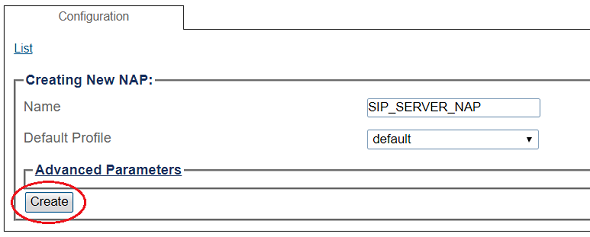
1- Click NAPs in the navigation panel
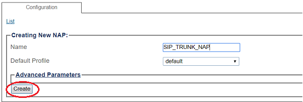
2- Click Create New NAP
3- Create the new NAP:
- Enter a name for the NAP
- Click Create
4- Verify that the NAP was successfully created message appears
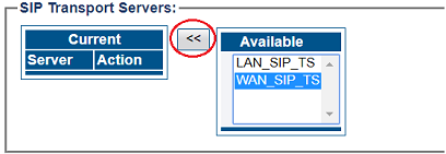
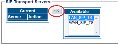
5- Associate a SIP transport server with the new NAP:
- Select a SIP Transport Server from the Available list
- Click "<<" to associate the WAN_SIP_TS with the NAP
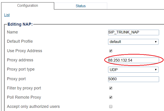
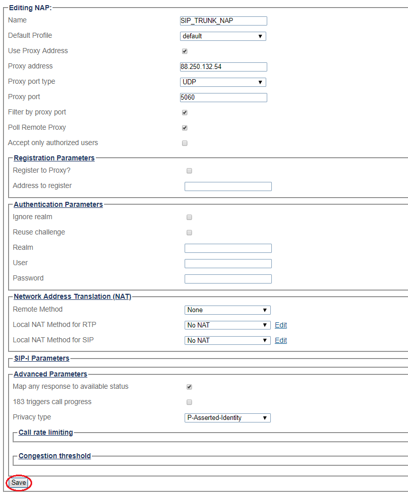
6- Enter SIP Trunk proxy address:
7- Associate a Port range with the new NAP:
- Select a port range from the Available list
- Click "<<" to associate WAN_Vlan:0 Port range with the NAP
8- Configure settings for the following parameter groups as required:
- Registration Parameters
- Authentication Parameters
- Network Address Translation
- SIP-I Parameters
- Advanced Parameters
- Click Save
SIP NAP Configuration for Local Area Network
To create a new NAP:
1- Click NAPs in the navigation panel
2- Click Create New NAP
3- Create the new NAP:
- Enter a name for the NAP
- Click Create
4- Verify that the NAP was successfully created message appears
5- Associate a SIP transport server with the new NAP:
- Select a SIP Transport Server from the Available list
- Click "<<" to associate the LAN_SIP_TS with the NAP
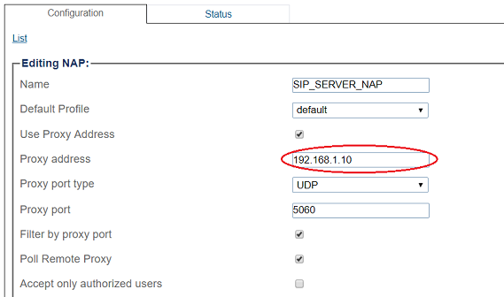
6- Enter SIP Server proxy address:
7- Associate a Port range with the new NAP:
- Select a port range from the Available list
- Click "<<" to associate LAN_Vlan:0 Port range with the NAP
8- Configure settings for the following parameter groups as required:
- Registration Parameters
- Authentication Parameters
- Network Address Translation
- SIP-I Parameters
- Advanced Parameters
- Click Save
Access Control List
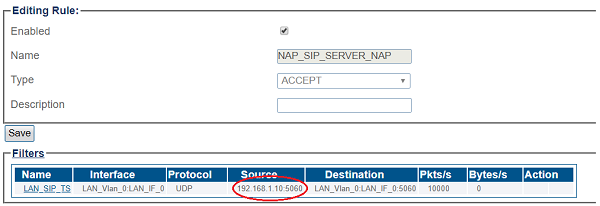
ProSBC will automatically create Access Control List for each NAP you created.
If you double click one of the created ACL, you will see ProSBC only accept the calls if the source IP matches. In this sample; the calls from 192.168.1.10 will be accepted only.
Call Route
You must set up call routing for your system. Call routing refers to the ability to route calls based on criteria such as origin, destination, time of day, service provider rates, and more.
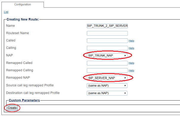
Route Configuration for SIP Trunk to SIP Server
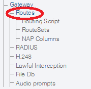
1- Click Routes in the navigation panel
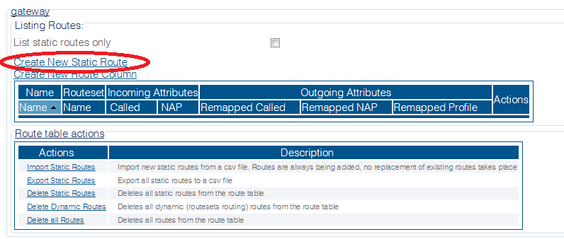
2- Click Create New Static Route
3- Create the new route:
- Enter a RoutesetName for the route
- Select SIP_TRUNK_NAP, to match calls from Trunk NAP
- Select SIP_SERVER_NAP
- Click Create
4- Verify that the " Route was successfully created" message appears and that the new route is listed in the Routeset list
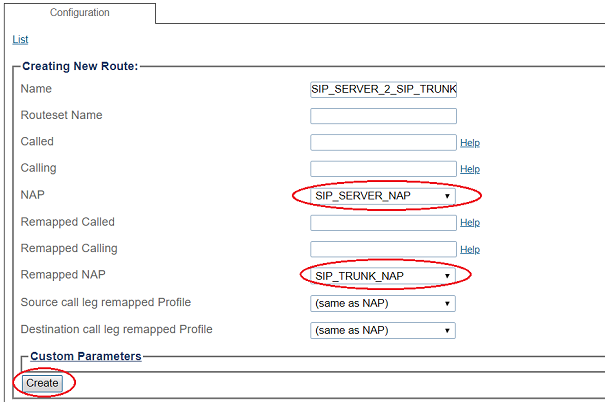
Route Configuration for SIP Server to SIP Trunk
1- Click Routes in the navigation panel
2- Click Create New Static Route
3- Create the new route:
- Enter a RoutesetName for the route
- Select SIP_SERVER_NAP, to match calls from Trunk NAP
- Select SIP_TRUNK_NAP
- Click Create
4- Verify that the " Route was successfully created" message appears and that the new route is listed in the Route set list
Activating the Configuration
Changes made to the configuration of the ProSBC units are stored in the OAM&P Configuration and Logging database. In order for changes to be used by the system, they must first be activated. This is done at the system level and accessed from the Navigation panel.
Check the following link for activating the configuration;
Toolpack:Activating_the_Configuration_D

