MTP2:Architecture
(added graphic) |
(clean up) |
||
| Line 2: | Line 2: | ||
| − | [[Image:MTP2-architecture.jpg| | + | [[Image:MTP2-architecture.jpg|700px|MTP2 architecture schematic]] |
Revision as of 10:57, 25 August 2009
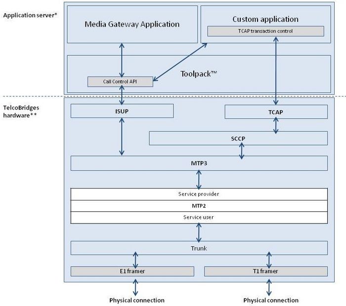
MTP Level 2 defines the functions and procedures of the signaling system for providing reliable transfer of signaling messages over a signaling link. The MTP2 layer is a service provider to the MTP3 Link layer. The MTP2 layer is a service user of line interfaces / line services” as seen in the shown in the figure below.
MTP2 can be used in conjunction with an above local MTP3 layer and can be used as a standalone and communicates with remote MTP3 layer (host application). See the connection mode table in the MTP2 Configuration section.
A MTP2 Link must be associated with one Trunk instance. It’s a 1-to-1 association. MTP Level 2 defines the functions and procedures of the signaling system for providing reliable transfer of signaling messages over a signaling link.
IMPORTANT NOTE: It is important to ensure that the received and transmitted clocks of the Trunk were synchronized. This can be useful for removing/limiting undesirable FIB and BSN errors. See section “Clock Configurations” in the TB640 user’s guide.
Priorities
No pre-emption of data occurs in the process of being transmitted or requiring retransmission. Only a single congestion priority is supported for ANSI and ITU. For a TTC/NTT link, transmitted data buffers are prioritized based on the priority indicated by MTP Level 3.
Flow control
The MTP Level 2 software regulates data flow when resource utilization (such as buffer pool size or queue length) reaches specifies thresholds. For each threshold, MTP Level 2 performs one of the following actions:
- Informs the layer manager about flow control.
- Sends a link status signal unit with status "B" (busy).
- Sends a flow control indication to the upper layer.
The MTP Level 2 software prevents deadlocks and overload conditions from occurring.
