Toolpack v2.2:Create an ISUP User Part
(Created page with 'The Userpart is the container for the multiple ISUP interfaces. One Userpart is required for each protocol variant. multiple ISUP userpart can be instantiated within a single IS…')
Newer edit →
Revision as of 17:24, 16 October 2009
The Userpart is the container for the multiple ISUP interfaces. One Userpart is required for each protocol variant.
multiple ISUP userpart can be instantiated within a single ISUP protocol layer. This allows a user application to interface with multiple SS7 ISUP protocol variants at the same time. Only one ISUP userpart is required for a specific variant as it can be assigned to multiple ISUP networks.
A Userpart can easily be seen as a protocol variant that a host application wants to use on the SS7 network.
To create an ISUP Userpart
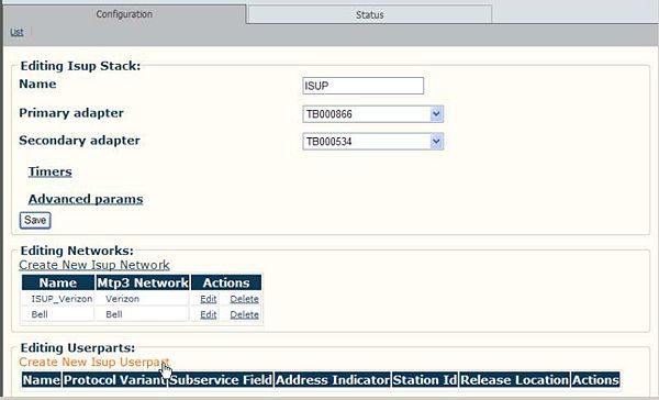
1. Click 'Create New ISUP User Part' to access the ISUP configuration window.
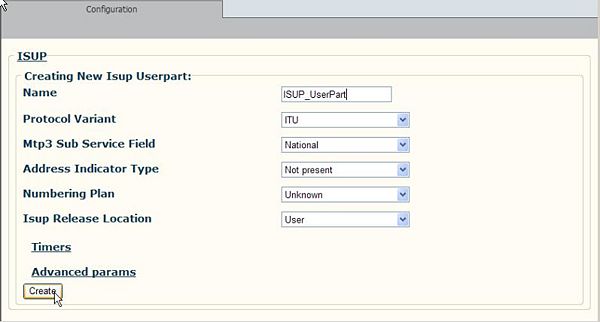
2. Enter a name for the ISUP user part.
- Select a protocol variant
- Click 'Create' to save the changes
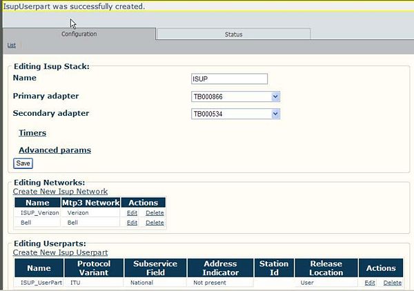
3. Verify that the 'ISUP Userpart was successfully created' message appears.
Description of parameters
- The Protocol variant parameter is used specify which protocol is going to be used to interact with peer ISUP layers. Allowed values are:
| Protocol variant | Description |
|---|---|
| ANSI 88 | Protocol follows specification "T1.113 (1998)" |
| ANSI 92 | Protocol follows specification "T1.113 (1992)" |
| ANSI 95 | Protocol follows specifications "T1.113.1 – T1.113.4 (1995)" |
| Telcordia | Protocol follows specifications "GR-317 and GR-394" |
| ITU | Protocol follows specifications "Q.761 - Q.764 (1993)" |
| ITU 97 | Protocol follows specifications "Q.761 – Q.764 (1997), Q.763 Addendum 1 (05/1998), Q.765 ISUP ASE module (05/1998) Q.767, ITU 1991" |
| Singapore | Protocol follows specification "Singapore Telecom, Common Channel Signaling System N.7, Singapore Telecom, 1988" |
| Q767 | Protocol follows specification "Q.767 (1991)" |
| NTT | Available on demand only. |
- The Sub-service field parameter is used to specify which type of network the protocol layer stands on (national or international). The SSF parameter is included in every ISUP MSUs sent and received from the SS7 network. Filtering according to this field can be activated/deactivated using the MTP3 'general configuration' parameter. Allowed values are:
| Sub-service field | Description |
|---|---|
| International | Messages sent by the layer will concern international traffi |
| National | Messages sent by the layer will concern national traffic |
| NAT Reserved | Reserved for national use |
- The Automatic calling number insertion parameter is used to instruct the ISUP userpart to insert the “calling party number IE” automatically in outgoing IAM MSUs if the host request does not already includes it. The default data is taken from the 'Station ID configuration' parameter.
- The Calling number verification parameter is used to instruct the ISUP userpart to validate if all calling party numbers IEs received from the host are equal to the default data from the station ID configuration parameter szSig. If the IE is not identical, the call will be refused by the ISUP layer.
- The Calling address indicator parameter is used to identify the type of number used in the 'Station ID' parameter. This value is mapped to the “Nature of address indicator” field of the “called party number” IE (refer to specification Q.763E, section 3.10 b). Allowed values are:
| Calling address indicator | Description |
|---|---|
| Not present | Used only when the default station ID is not configured |
| Subscriber number | Number represents a subscriber number (national use) |
| National number | Number represents a national (significant) number |
| International number | Number represents an international number |
- The Numbering plan parameter is used to identify the numbering scheme for the 'Station ID' parameter. This value is mapped to the 'Numbering plan indicator' field of the 'called party number' IE (refer to specification Q.763E, section 3.9 d). Allowed values are:
| Calling numbering plan | Description |
|---|---|
| Unknown | Unknown numbering scheme |
| ISDN | ISDN/Telephony numbering according to E.164/E.163 |
| Tel | Telephony numbering according to E.163 |
| Data | Data numbering according to X.121 (national use) |
| Telex | Telex numbering according to F.69 (national use) |
| National | National standard numbering |
| Private | Private numbering |
| Ext | Reserved for extension |
- The Station ID parameter contains the default “calling party number” signals that is used in automatic CID insertion (see fCallingNbInsertion) and calling number verification (see fCallingNbVerification). The digit string is coded in ASCII and will be converted to BCD encoding by the stack as specified in Q.763E, section 3.10 g).
- The Presentation restricted indication parameter instructs the ISUP userpart to force (set) the presentation restricted flag of the calling party number IE of all incoming call events.
- The Presentation restricted incoming parameter instructs the ISUP userpart to force (set) the presentation restricted flag of the calling party number IE of all incoming IAM MSUs.
- The Presentation restricted outgoing parameter instructs the ISUP userpart to force (set) the presentation restricted flag of the calling party number IE of all outgoing IAM MSUs.
- The Request calling number parameter instructs the ISUP userpart to send an INR MSUs when it receive incoming call where there is no calling number IE. This option must be disabled for variants not supporting INR (i.e. NTT).
- The Call modification parameter is used for the ISUP userpart to allow for call modification.
- The maximum user to user message length parameter is used to set the maximum size (in bytes) allowed in MSUs. If set to zero, the user-to-user information is removed from all MSUs. Allowed values are from 0 to 255.
- The Pass-on allow parameter is used instruct the ISUP layer to allow unrecognized MSUs to be passed up or down. This field is not used by ANSI variants.
- The Release location parameter is used to fill the release location indicator of the cause IE when the ISUP layer automatically releases calls (i.e. when there is a timer expiry). Allowed values are:
| Release location | Description |
|---|---|
| User | User |
| Private network local user | Private network serving local user |
| Public network local user | Public network serving local user |
| Transit network | Transit network |
| Public network remote user | Public network serving remote user |
| Private network remote user | Private network serving remote user |
| Local interface | Local interface controlled by this link |
| International network | International network |
| Network internetworking | Network beyond internetworking point |
| No information | No information available |
- Regarding the Timer configuration parameters, all timer values must be expressed in milliseconds. Those timers are defined as follows:
| Timer | Description |
|---|---|
| T1 Timer | RELEASE message sent. Terminated normally at the receipt of an RLC message. Typical values are 15 to 60 seconds. |
| T2 Timer | SUSPEND message receive by controlling exchange. Terminated normally when RESUME (user) is received at the controlling exchange. Typical value is 3 minutes. |
| T5 Timer | INITIAL RELEASE message sent. Terminated normally at the receipt of the RLC message. Typical values are 5 to 15 minutes. |
| T6 Timer | SUSPEND (network) received by controlling exchange. Terminated normally at the receipt of RESUME (network) or RELEASE. Typical value is 1 second. |
| T7 Timer | LATEST ADDRESS message sent. Terminated normally when the condition for normal release of address and routing information is met. Typical values are 20 to 30 seconds. |
| T8 Timer | INITIAL ADDRESS message received by incoming international exchange. Typical values are 10 to 15 seconds. |
| T9 Timer | LATEST ADDRESS message sent by the outgoing international exchange. Terminated normally at the receipt of answer. Typical values are 90 to 180 seconds. |
| T27 Timer | Waiting for continuity rechecks. Terminated normally when the CONTINUITY CHECK REQUEST message is received. . Typical value is 4 minutes. |
| T31 Timer | Release of ISUP signaling connection based on connection oriented SCCP. Call reference is frozen during this period and is reusable after the timer expiry. Typical values are more than 6 minutes. |
| T33 Timer | Information request sent. Terminated normally when INF message is received. Typical values are 12 to 15 seconds. |
| T34 Timer | Waiting for continuity after rechecks (ANSI88, ANSI92 and Telcordia). For the ITU segmentation timer, see un32T36Timer. Typical values are 2 to 4 seconds. |
| T36 Timer | Awaiting for another segmented message. For ITU-T, ETSI and FTZ, this timer substitute for the T34 (ANSI). Typical values are 10 to 15 seconds. |
| CCr Timer | Continuity recheck timer. Typical value is 20 seconds. |
| Ex Timer | Exit to be sent (ANSI and Telcordia). The values are dependent upon the network. |
| CCR Timer | Awaiting LPA message after having sent CCR (ANSI88, ANSI92 and Telcordia). Typical value is 2 seconds. |
| CRM Timer | Circuit reservation sent, waiting for reservation acknowledge (ANSI92 and Telcordia). Typical values are from 3 to 4 seconds. |
| CRA Timer | Circuit reservation acknowledge sent, waiting for IAM (ANSI92 and Telcordia). Terminated normally when IAM is received.. Typical value is 10 seconds. |
| ECT Timer | Explicit call transfer, waiting for LOOP PREVENTION RESPONSE message (ETSI, ETSI V3 and ITU97). Typical value is 1 second. |
| RELRSP Timer | Waiting for release response timer. It is used to account for loss of release response primitive. Typical values are system-dependent. |
| FNLRELRSP Timer | Waiting for release response timer. It is used to account for the loss of release response primitive. If the release response from the host application is not received before the expiry of this timer, circuit reset is locally initiated by the ISUP userpart. Typical values are system-dependent. |
NOTE: The following timers are not required for the UK: T8, T27, T31, T36. The value of T33 is 5-15s. If Timer (T33) matures, the call shall continue in the normal way.


