Tmedia 1+1
TelcoBridges Tmedia 1+1 answers service providers’ needs for five nines reliability, offering a redundant gateway that ensures high-availability. This 1+1 feature set is available for the Tmedia TMG800, TMG3200 and TMG7800, creating a redundant system from 1 to 64 T1/E1s, 1 to 3 DS3s or 1 STM1.
Our clients are looking to ensure that their VoIP systems are as infallible as their TDM networks, and TelcoBridges 1+1 provides that high level of redundancy and high availability they need to remain competitive.
What does TelcoBridges mean when they say their system is redundant?
TelcoBridges Tmedia 1+1 systems provide power redundancy, packet network redundancy and facility protection.
Contents |
Goals of the Tmedia 1+1 system
- Protect the system (no loss of service) in case of failure of a Tmedia unit
- Reduce down-time when upgrading the software or hardware of a Tmedia 1+1 system
Available configurations
- TMG800 1+1 system (T1/E1)
- TMG3200 1+1 system (STM1, DS3, T1/E1)
- TMG7800
Components of the Tmedia 1+1 system
The Tmedia 1+1 system is made of two Tmedia units. In case of failure of the active unit, the exact configuration that was on the active Tmedia unit gets copied onto the standby unit. The standby unit is activated, and continues to route the calls.
With TMG800 or TMG3200, the Tmedia 1+1 consists of
- A Tmedia Standard unit
- A Tmedia +1 "secondary" unit
- A 1+1 patch panel to connect TDM network to both TMedia units
With TMG7800, the Tmedia 1+1 consists of
- A primary TMG7800-ctrl server
- A secondary TMG7800-ctrl server
- Multiple pairs of TMG7800 Telecommunication units (T1/E1, DS3, or STM1)
- Multiple 1+1 patch panels (one per pair of TMG7800 Telecommunication units)
Types of Tmedia units that can be purchased
- TMG800 Standard (primary) unit
- Can be used as a standalone unit, or part of a 1+1 system.
- TMG800 1+1 (secondary) unit.
- Also comes with the 1+1 patch panel and cables
- Available at a discount price.
- Can only be used for 30 days when the primary unit is missing. Failed unit must be replaced/repaired during that period.
- TMG3200 Standard (primary unit)
- Can be used as a standalone unit, or part of a 1+1 system.
- TMG3200 1+1 (secondary) unit
- Also comes with the 1+1 patch panel and cables
- Available at a discount price.
- Can only be used for 30 days when the primary unit is missing. Failed unit must be replaced/repaired during that period.
- TMG3200 Spare unit.
- Can be used to replace a failed primary or secondary unit.
- Available at a discount price.
- Can only be used for 30 days upon activation. Failed unit that it replaces must be replaced/repaired during that period.
- TMG7800-ctrl unit
- The same type of unit is used both as primary or secondary server
- TMG7800 Telecommunication unit (T1/E1, DS3 or STM1)
- The same type of unit is used both as primary or secondary Telecommunication unit
To ensure complete protection, TelcoBridges recommends the purchase of a spare unit to go along with your 1+1 solution so the 1+1 system. This allows immediate replacement of a failed unit of the 1+1 system while it's being repaired by TelcoBridges.
Network connection between units of the Tmedia 1+1 system
All units of the Tmedia 1+1 system need to be connected together using two Ethernet networks. These two networks must be:
- Independent Ethernet networks
- two for redundancy
- independant to avoid interferences between them
- Private (No up-link to the LAN)
- to avoid interferences with other equipments
- to isolate multiple Tmedia 1+1 systems from each other)
Networking configuration for TMG800 1+1 system
Each unit of the TMG800 1+1 system has only two Ethernet interfaces (named voip0 and voip1). They must be shared for network communication with external world (SIP, RTP, Sigtran, H.248), and with private communication between the two TMG800 units of the system.
Two private VLans must be created to establish private and redundant network communication path between the two units:
- VLan IDs are provided to TMG800 units upon initial configuration through Web Portal
- VLans configuration in the Ethernet switches that the TMG800 units are connected to must be
- Done before starting the TMG800 units for the first time by network operator
- Must be private to ONLY the two ports the TMG800 units are connected to

For more information, please refer to TMG800 1+1 installation guide.
Networking configuration for TMG3200 1+1 system
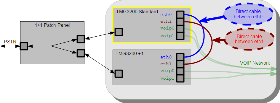
Each unit of the TMG3200 1+1 system has four (4) physical Ethernet interfaces.
- voip0 and voip1 for network communication with external world (SIP, RTP, Sigtran, H.248)
- eth0 and eth1 for private communication between the units
The network configuration for TMG3200 1+1 system is quite simple: Simply connect the eth0 and eth1 ports of the two units back-to-back using standard Ethernet cable:

For more information, please refer to TMG3200 1+1 installation guide.
Networking configuration for TMG7800 1+1 system
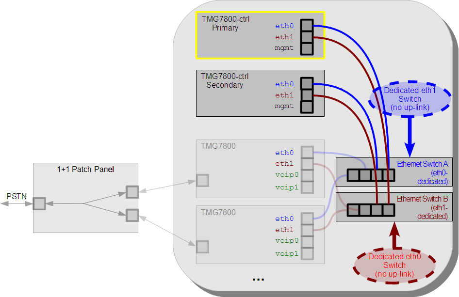
The two servers (TMG7800-ctrl) units of the TMG7800 1+1 system have three (3) Ethernet ports:
- mgmt to access configuration Web Portal, or SSH connection with the unit. It can also be used for H.248.
- eth0 and eth1 for private communication between all other units of the system (TMG7800-control servers, and TMG7800 Telecommunication units)
Each TMG7800 Telecommunication units have four (4) Ethernet ports that can be used:
- voip0 and voip1 for network communication with external world (SIP, RTP, Sigtran, H.248)
- eth0 and eth1 for private communication with all other units of the system (TMG7800-control servers, and TMG7800 Telecommunication units)
It is mandatory that all eth0 ports of the system are connected together through a dedicated Ethernet switch.
It is mandatory that all eth1 ports of the system are connected together through another dedicated Ethernet switch.
These two Ethernet switches must not be connected to each other, and should ideally also not have any UpLink to the LAN (to minimize risks of interference with network traffic on the LAN).

For more information, please refer to TMG7800 1+1 installation guide.
How redundancy is achieved
The TMedia system contains
- Host server, running call control applications, web portal, and other OAM-related applications
- Telecommunication unit, running protocol stacks, and having hardware resources to process voice (TDM, or VOIP)
Notes:
- The TMG800 unit contains both the host server and the Telecommunication unit in the same box.
- The TMG3200 unit contains both the host server and the Telecommunication unit in the same box.
- The TMG7800 has separated server (TMG7800-ctrl) and Telecommunication units (TMG7800) for scalability.
Redundancy of the applications
- The applications running on the host server are redundant by having one copy of each application running on each unit.
- In case of failure of an application, the corresponding application on the other unit is activated to replace the failed application.
- In case the whole host server unit fails, all applications on the other unit are activated.
Redundancy of the Telecommunication units
- Telecommunications units used in pairs (1+1)
- Both are connected to the TDM network, and to the IP network
- One is active (driving the signal on the TDM network, assigned an IP address on the VOIP network)
- One is standby (not driving the TDM network, no IP assigned on the VOIP network)
- When one unit fails
- the other unit is activated with the exact same configuration as the primary units
- the other unit starts driving the TDM network
- the other unit is assigned the IP address (moved from the primary) on the VOIP network)
