FreeSBC:Networking
Contents |
Requirements
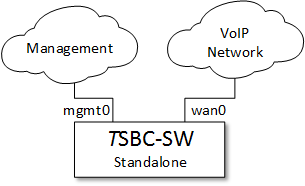
TSBC-SW deployments require a minimum of two networks for initial configuration. The first network will be used as a local management interface to access the instance using the web portal (HTTP/HTTPS) and SSH access. The second network will transport the actual incoming and outgoing VoIP streams (signaling and media) that the TSBC-SW will process.
The TSBC-SW can handle up to 32 different physical interfaces which allows numerous different deployment configuration to fit any networking needs.
Network setups
Depending on the technical requirements of a particular deployment, a TSBC-SW can be installed as a standalone or protected (1+1) system. These options have different network needs to fulfill their functions. In addition to redundancy, the support of external transcoding equipment with the TSBC-SW also adds to the network requirements. The following section depict the different supported network configurations.
Redundancy
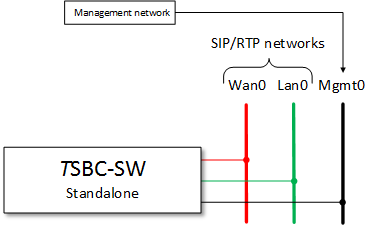
Standalone without transcoding
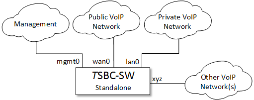
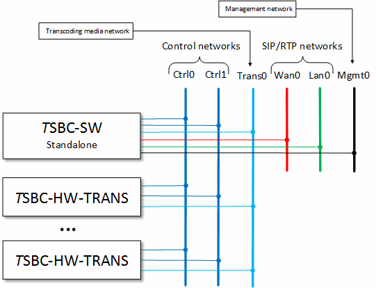
In this configuration, the TSBC-SW does not have any backup instances nor is using any transcoding equipment. Thus, the only networks needed are the management network along with one or many VoIP networks to carry the data streams. In the example below, the TSBC-SW was deployed with one "public" network named 'wan0' and one "private" network named 'lan0'.
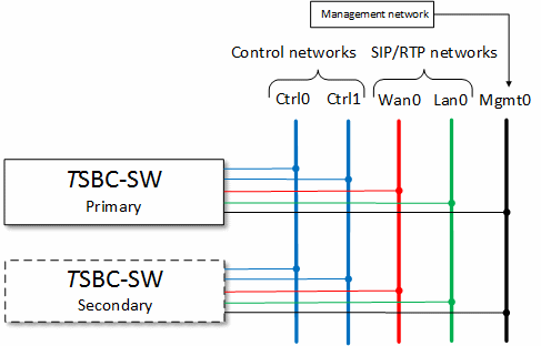
1+1 without transcoding
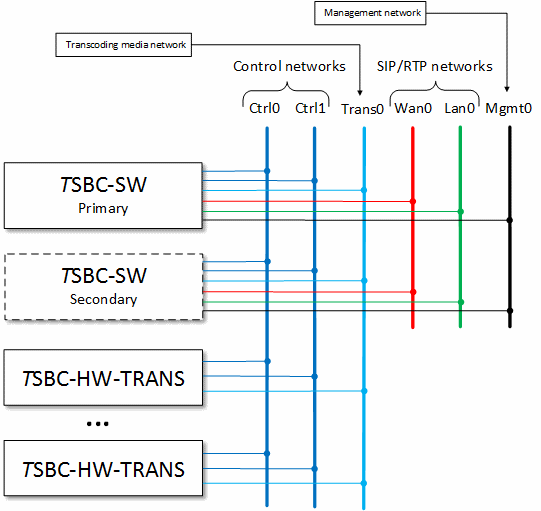
In this configuration, the TSBC-SW system is deployed with two instances providing an active/standby redundancy scheme without any transcoding equipment. In addition to the regular networks required shown in the previous example (management and VoIP networks), the two instances need access to two control separate networks allowing to exchange check-pointing information. These networks are private to the TSBC-SW and should never be shared or be visible to non-TelcoBridges equipment.
Although a single control network is sufficient to achieve the 1+1 function, it is not recommended by TelcoBridges unless the operator fully controls all network segments and can guarantee it can never fail at both the physical and routing (IP) layer. In most cases, having two separate control networks going through independent network devices, switches and routers is the only way to ensure 'no single point of failure'.
Transcoding
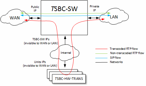
The TSBC-SW session border controller should be the only equipment facing the different networks to ensure proper protection and monitoring. In that sense, any transcoding units deployed (TSBC-HW-TRANS) will never be visible from data networks handled by the SBC. The TSBC-SW will require three internal networks to reach the transcoding units: two control networks and one media network. The control networks are the same as those deployed for redundant systems while the media network will contain all the VoIP traffic coming in or out of the transcoding units.
Standalone with transcoding
Combining the standalone network requirements to the transcoding network needs, the deployment of such a system requires multiple networks as depicted below:
1+1 with transcoding
Combining the redundant network requirements to the transcoding network needs, the deployment of such a system requires multiple networks as depicted below:
Network device discovery
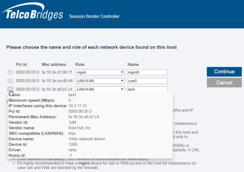
Once all networks have been physically (or virtually) connected to the TSBC-SW instance, the system can be started. Upon first bootup (or after an operator initiated 'network device role' reset), the TSBC-SW web portal will show a network device assignation page. As the TSBC-SW cannot guess what type of traffic the operator wants to process on any given network, this page is used to identify the role of each detected devices. As described above, the role can be any of the following three: control, management or VoIP traffic (named LAN/WAN). Once the role is selected, the operator can enter a name for each. Every configured/detected physical network device will then appear as a 'physical port' in the 'IP Interace' tab in the web portal.
The operator can click on the '+' sign to get more information about a specific network device. These information are helpful to match detected networks with the real network based on these characteristics (IP, driver type, etc).
