Tapping patch panel
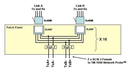
The Tapping Patch Panel connects the Tmonitor TM1000 network monitoring device to the T1/E1 signals to be monitored. It provides non-intrusive monitoring of the T1/E1 signals while passing through the actual T1/E1 signals. The device includes high-impedance circuits to connect to the active T1/E1 signals such that it can probe the electrical signals while minimizing disturbances on the actual signals.
The connected signals are routed to the TM1000 which receives them to detect and capture SS7 messages and HDLC-like packets.
The Tapping Patch Panel is a passive device. Each Tapping Patch Panel consists of 32 female RJ45 connectors for the connection of up to 16 T1/E1 links to be monitored.
For each T1/E1 link, the patch panel passes through the T1/E1 signal while tapping the signals for monitoring by TM-1000 Network Probe. The device features configurable high-impedance circuits individually for each T1/E1 link.
Contents |
Technical Specifications
Physical Interfaces
- Front Panel
- 32 RJ45 female T1/E1 input connectors
- 16 in and 16 out
- Rear Panel
- 2 SCSI-3 female output connectors (to TM-1000 Network Probe)
Standards
- Non-Intrusive Monitoring
- Protected E1 monitoring: ITU-T G.772
- Protected T1 monitoring: ANSI T1.102-1993
Mechanical
- 1U 19-inch rackmount
- Recessed
Environmental
- Operating: 0 to +50º C, 0 to 95% non-condensing, relative humidity
- Storage: -20 to +75º C, 0 to 95% non-condensing, relative humidity
