Toolpack v2.2:Create an ISUP Interface
The ISUP interface entity creates a binding within the ISUP layer of a particular variant, a specific network and an OPC/DPC pair to which circuits can be assigned to.
The ISUP interface contains the circuit identifier codes (CICs) within the ISUP Userpart. One interface is created for each similar grouping of CICs within one Userpart protocol variant.
To create an ISUP interface
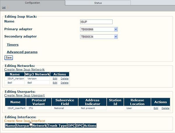
1. Click 'Create New ISUP Interface'.
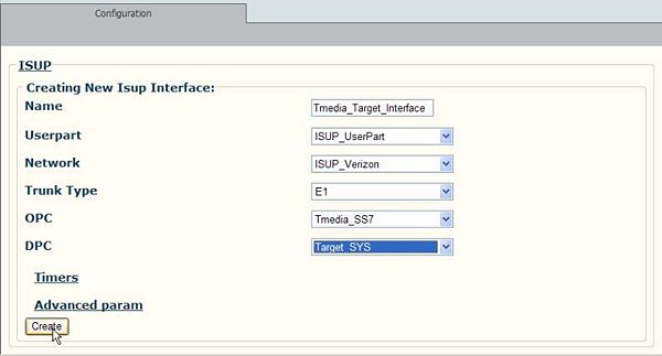
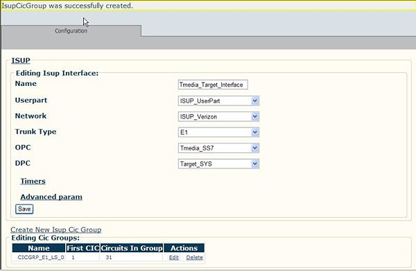
2. Provide a name for the ISUP Interface.
- Select a previously created ISUP Userpart
- Select a previously created network
- Select the originating and destination points codes
- Click Create to save the changes
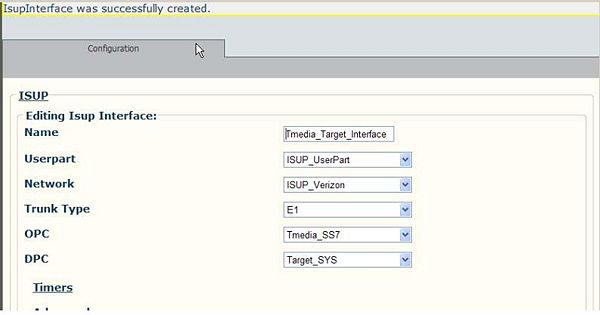
3. Verify that the 'ISUP Interface was successfully created' message appears.
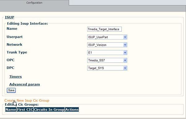
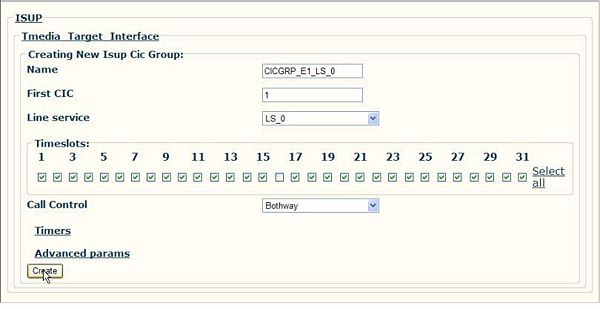
4. Click 'Create New ISUP CIC Group' to access the CIC configuration window.
5. Provide a name for the CIC Group.
- Indicate the number of the first CIC in the group.
- Select the line service and indicate the timeslots that are to be use by this CIC group.
- Click 'Create' to save the changes.
6. Verify that the 'ISUP CIC Group was successfully created' message appears.
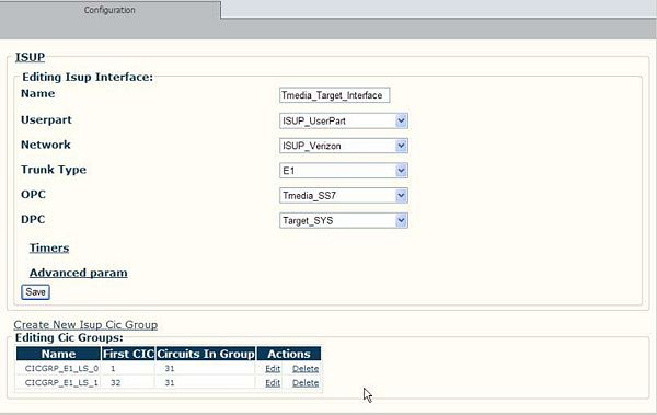
A second CIC Group is shown, added to the CIC group listing.
Description of parameters
General explanation of the parameters of configuration:
- The ISUP userpart parameter is used to specify within which userpart this interface instance is to be created
- The ISUP network parameter is used to specify within which userpart this interface instance is to be created
- The Trunk type parameter represents the type of digital path used between the near-end exchange and far-end exchange. This field is used when ISUP validate a received CAM parameter, or when it fills a CAM parameter and checks the Q.763 table 3 for a non-since rate connections. ISUP uses this field for ANS95, ITU97 and ETSI v3 variants. Allowed values are:
| Trunk type | Description |
|---|---|
| E1 | Digital trunk type is E1 |
| T1 | Digital trunk type is T1 |
NOTE: In ANSI95, the trunk type can only be T1.
- The Origin point code parameter (OPC) contains the point code (address) of the local SS7 node to which the ISUP interface is bounded to. The point code format must follow the switch variant configured in the ISUP userpart. See MTP2:Destination Point Code for proper point code length.
- The Destination point code parameter (DPC) contains the point code (address) of the remote SS7 node to which the ISUP interface is bounded to. The point code format must follow the switch variant configured in the ISUP userpart. See MTP2:Destination Point Code for proper point code length.
- The Pause action parameter instructs the ISUP interface what to do with calls when the destination SS7 node becomes ‘paused’ (not accessible). This parameter is reconfigurable. Allowed values are:
| Pause action | Description |
|---|---|
| Clear all | All calls on the interface’s circuits are released then the destination point code becomes unavailable. |
| Clear transient | All calls with a non active state on the interface’s circuits are released then the destination point code becomes unavailable |
| Clear after timer | All calls on the interface’s circuits are released after the Timer expiry |
- The Availability test parameter determines whether or not the ISUP interface should generate a circuit validation test on a circuit upon reception of an MTP-RESUME indication. This option is only valid for ANSI95.
- The Multi rate table check parameter tells whether or not the ISUP interface should check the Table 3 (part 1 or part 2) in ITU97 Q.763 for multi-rate connection type calls and fixed contiguous Nx64 calls. The ISUP userpart uses this field to validate the starting CIC, in case of multi-rate connection type calls and fixed contiguous Nx64 calls, if the calls begin on the specific circuits. This field is used in ITU97, UK and ETSI v3 variants. Allowed values are:
| Multi-rate check | Description |
|---|---|
| Table 3 Part 1 | Validate the start CIC for multi-rate calls as per Table 3 part 1 Q.763. |
| Table 3 Part 2 | Validate the start CIC for fixed contiguous calls as per Table 3 part 2 Q.763 |
- The SLS selector parameter instructs the ISUP interface about the SLS selection algorithm to use. Allowed values are:
| SLS selector | Description |
|---|---|
| Load distribution | SLS is selected to optimize load distribution |
| by CIC | SLS is selected according to CIC |
- The SLS range parameter instructs the ISUP interface to use a defined range of SLS values. This parameter is only used for ANSI88, ANSI92, ANSI95 and Telcordia. Allowed values are:
| SLS range | Description |
|---|---|
| 5 Bits | SLS values will be from 0-31 |
| 8 Bits | SLS values will be from 0-255 |
- The Timer configuration parameters The timers have the following definitions. All timers are reconfigurable. All timer values must be expressed in milliseconds:
| Connection mode | Description |
|---|---|
| T4 Timer | RELEASE message sent. Terminated normally at the receipt of an RLC message. Typical values are 15 to 60 seconds. |
| Pause Timer | SUSPEND message receive by controlling exchange. Terminated normally when RESUME (user) is received at the controlling exchange. Typical value is 3 minutes. |
| State Enquiry Timer | Query DPC state from MTP3 layer when ISUP interface is not available. Typical value is 15 seconds. |
NOTE: As specified in section 6.1.3, an ISUP interface can only be part of a single ISUP userpart. On the other hand, multiple circuits can be attached to the same interface instance. Those circuits represent the voice channels available between the local SS7 node and the remote SS7 node.
