Toolpack v2.2:Create an MTP3 Route
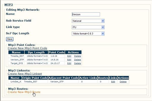
MTP3 routes are built to route traffic from previously created point codes using linksets.
To create an MTP3 Route
1. Click 'Create New MTP3 Route'
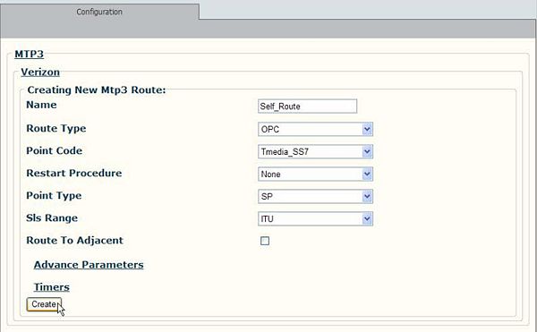
2. Provide a name that indicates this is your self route.
- Select OPC for an origin point code. (DPC is for a route leading away from you).
- Select a point code and click Create to create the MTP3 Route
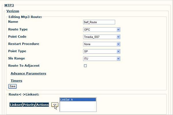
3. Click the name of a linkset then use the << button to assign it to the newly created route.
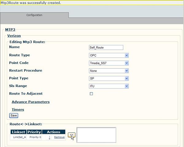
4. Verify that the linkset is assigned to the route.
Note: This procedure for the MTP3 Route is repeated to define the routes to the adjacent and
target point codes. In addition, when configuring the adjacent route, make certain that the 'Route To Adjacent' box is checked.
Description of parameters
- The Destination point code (DPC) parameter specifies the point code of the node where the route is terminating
NOTE: Default routing: Note that destination point code 0.0.0 is reserved for default routing. When no explicit route exists for a destination point code and default route 0.0.0 is present, the message is passed to MTP 2 for delivery in place of being dropped. Default routing can be used for routing of outbound messages only (direction parameter equal to 'Down'.
- The Signaling point type parameter specifies whether the point code under configuration is an SP or an STP. Allowable values: see Table 14 - MTP3 signaling point types Table 18 - MTP3 signaling point types.
- The Direction parameter (Direction) specifies whether the point code under configuration is self-point code or remote SS7 point code. A route configuration exists for each point code, including Trillium's; when a route for Trillium's own point code is configured, a direction of 'Up' is used. For remote point codes in the SS7 network, a direction of 'Down' is used. Allowable values:
| Direction | Description |
|---|---|
| Up | Local DPC |
| Down | Remote DPC |
NOTE: If multiple OPC capability is required, the number of routes configured with direction as 'Up' should be equal to the number of OPCs representing the Trillium node/Gateway.
- The Route timers configuration parameters have the following definitions:
| Message priority | Description |
|---|---|
| T6 Timer | Delay to avoid missequencing during controlled rerouting. Typical value is 800 milliseconds (0.8 seconds) |
| T8 Timer | Transfer prohibited inhibition timer. Typical value is 800 milliseconds (0.8 seconds) |
| T10 Timer | Route set test timer. Typical value is 30,000 milliseconds (30 seconds) |
| T11 Timer | Transfer restrict timer. Typical value is 30,000 milliseconds (30 seconds) |
| T19 Timer | TRA (Traffic Restart Allowed) timer. Not required for ITU 88. Same as T29 of ANSI. Typical value is 67,000 milliseconds (67 seconds) |
| T21 Timer | Waiting to restart traffic routed through adjacent SP |
| T18 Timer | Transfer restricted inhibition. Used for ANSI 88, 92 and 96 only. Typical value is 11000 milliseconds (11 seconds) |
| T25 Timer | Waiting for traffic restart allowed message" timer. Used for ANSI 88, 92 and 96 only. Typical value is 30,000 milliseconds (30 seconds) |
| TcTimer | Delay timer for remote congestion abatement. Used for TTC and NTT only. Typical value is 500 milliseconds (0.5 second) |
- The flag indicating Route to adjacent SP specifies whether the point code being configured is adjacent to Trillium node. This field is not reconfigurable. Allowable values are 'True' or 'False'.
NOTE: Must be 'False' if Direction is 'Up'.
- The Broadcast required flag specifies whether the route management messages for this destination are sent in a broadcast manner to other destinations in the network. This field is reconfigurable. Allowable values are 'True' or 'False'.
- The Restarting procedure required field is configured only for the point codes adjacent to Trillium's node. When MTP3 restores connectivity with an adjacent point code, it starts the adjacent restart procedure as recommended by this field. This field is reconfigurable. Allowable values: see Table 15 - MTP3 restart procedures Table 19 - MTP3 restart procedures.
NOTE: TTC and NTT do not support MTP3 restart procedure.
- Regarding the Number of SLSs for this point code parameter, the number of SLSs depends on the network for which the route is configured. This field is not reconfigurable. Allowable values are the following:
| SLS Ranges | Description |
|---|---|
| ITU | ITU, TTC and CHINA |
| ANSI 5bits | For networks which use 5 bits SLS |
| ANSI 8bits | For networks which use 8 bits SLS |
| NTT | NTT |
- Regarding Linkset selector bit(s) in SLS, this field needs to be configured only when the own point code is an STP. At an STP, for any incoming message which needs to be rerouted to the DPC indicated in the message, MTP3 chooses a linkset based on these bit(s) of SLS in the received message. This field is reconfigurable. Allowable values are:
- Linkset Selector
- BIT1
- BIT2
- BIT3
- BIT4
- Linkset Selector
If more than one bit needs to be used to choose a linkset, the above values can be ORed. For example, if at an ITU STP, the 2 LSBs of SLS need to be used for selecting a linkset, the lsetSel value should be configured as:
BIT1 | BIT1
The value should be chosen based on the incoming SLSs such that a fair distribution of load happens among the linksets towards the given destination.
Refer to Section A.5 in ITU Q.705 specification, "Explanatory Note from the Implementors Forum for Clarification of Load Sharing," for details on load sharing at an STP.
NOTE: For an NTT STP, this field should always be configured with TB640_SS7_MTP3_STP_SLS_SELECTOR_BIT2. For ANSI STPs, the last bit is used to choose a linkset (as per the specifications), hence this field should be configured to TB640_SS7_MTP3_STP_SLS_SELECTOR_BIT1.
NOTE: Reconfiguring this field in a live system while the point code is available may result in mis-sequencing.
- The Multi-message priority flag indicates whether multiple congestion priorities are supported for the destination or not. Allowable values are 'True' or 'False'. If the value is set to 'False, all the outgoing messages will be encoded with priority 0 irrespective of the priority received from the user part. This field is reconfigurable. If this field is set as 'False', no messages are dropped due to link congestion. Also if this field is 'False', the route set congestion cannot be performed and hence the Support Route Set Congestion Test flag should be set to 'False'.
NOTE: Should be set to 'True for ANSI networks and all national variants of ITU which require the support for multiple congestion states.
NOTE: Setting this option to 'True' with remote equipment NOT supporting it will result in some SS7 primitives being ignored by the remote switches. For example, outgoing IAMs will work (as its priority is always 0) but REL and RLC will be ignored. Thus, be very careful when activating this configuration parameter.
- The Route set congestion parameter indicates whether the route-set-congestion test needs to be performed or not on reception of a transfer controlled message. Allowable values are 'True' or 'False'. This field needs to be configured only for the networks which support multiple congestion priorities (ITU with national option, CHINA, TTC, NTT, and ANSI).
NOTE: For TTC and NTT networks, if this flag is set to 'False', the congestion status received in the transfer controlled message is stored and the timer Tc is started. On expiry of timer Tc the congestion status is cleared. For all other networks, the congestion status received in the transfer controlled message is not stored if this flag is set to 'False'. Support Route Set Congestion Test should be 'True' for ANSI and all other country variants where this is not an option.
- The Number of linkset parameter specifies the number of linksets required in the route
- The Linkset handle array parameter specifies the list handle of linksets to access this route
NOTE: For a self-route configuration (when the Direction parameter is set to 'Up'), we only need one linkset in such a route. It has no real meaning in the SS7 networks but the Trillium SS7 stack needs to get configuration parameter LinkType from Userpart to validate the SlsRange.
- The Linkset priority array parameter specifies the priority of the linksets for these route. The highest priority is 0. There must be at least one linkset with priority 0. If there are multiple linksets with different priorities for a node, then their priorities must be contiguous. For example, there can be no existing linksets with priority 0, 1, and 3 for a node (priority 2 missing).


